Orchestrating Traffic Signals
From ASAM spec to scenario controller — designing the tooling that let engineers orchestrate entire junctions without editing each traffic light individually.
Traffic controller grouping multiple signals into one orchestrated phase sequence
Impact
orchestration time for a 4–10 signal roundabout
increase in traffic-signal–based scenario creation post-redesign.
configuration errors and improved clarity in complex intersections — qualitative feedback from engineers.
Goal
Orchestrate complex traffic-signal behaviours on a map — including multi-lane vehicle interactions and pedestrian crossings — so engineers could build more realistic AV testing scenarios without editing each traffic light individually.
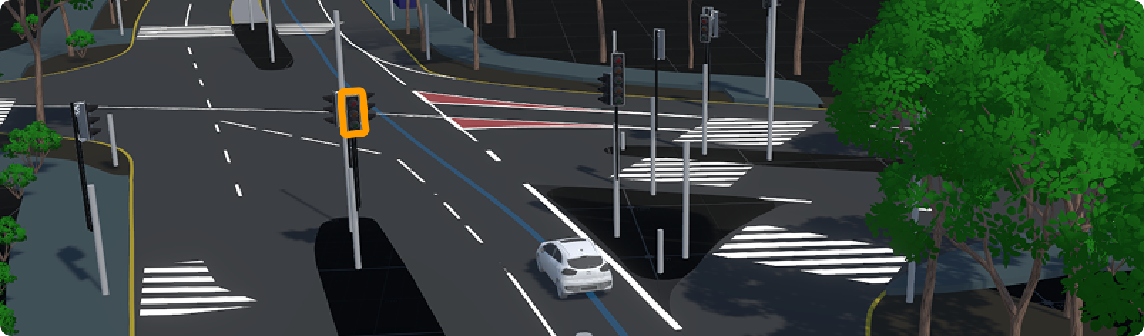
A single signal selected in Genie's 3D simulation world
From spec to daily use
The Genie Scenario Editor follows ASAM OpenSCENARIO 2, which allows traffic signals to be grouped under a single TrafficSignalController with synchronised phases and durations. On paper, a footnote. In practice, the gap between a feature that existed in a standard and one that worked for people authoring scenarios daily.
I sat with a Traffic Simulation Test Engineer as they built a junction scenario, watching them work through a roundabout signal by signal. They knew exactly what the junction needed to do — but couldn't get there without re-clicking a dozen lights, second-guessing whether each one was already synced. That gap between intent and tool capability, repeated across every scenario, was the real problem.
50 minutes to 2 hours — by hand
Engineers were building roundabouts with four to ten lights entirely by hand — select, set colour, set timing, repeat per signal, per phase. Nothing was linked or traceable. One mismatched phase could silently invalidate a scenario.
Key insight: engineers weren't short on information — they were drowning in irrelevant information, with no visible relationship between a controller, its lanes, and its crossings.
User journey
50 min – 2 hours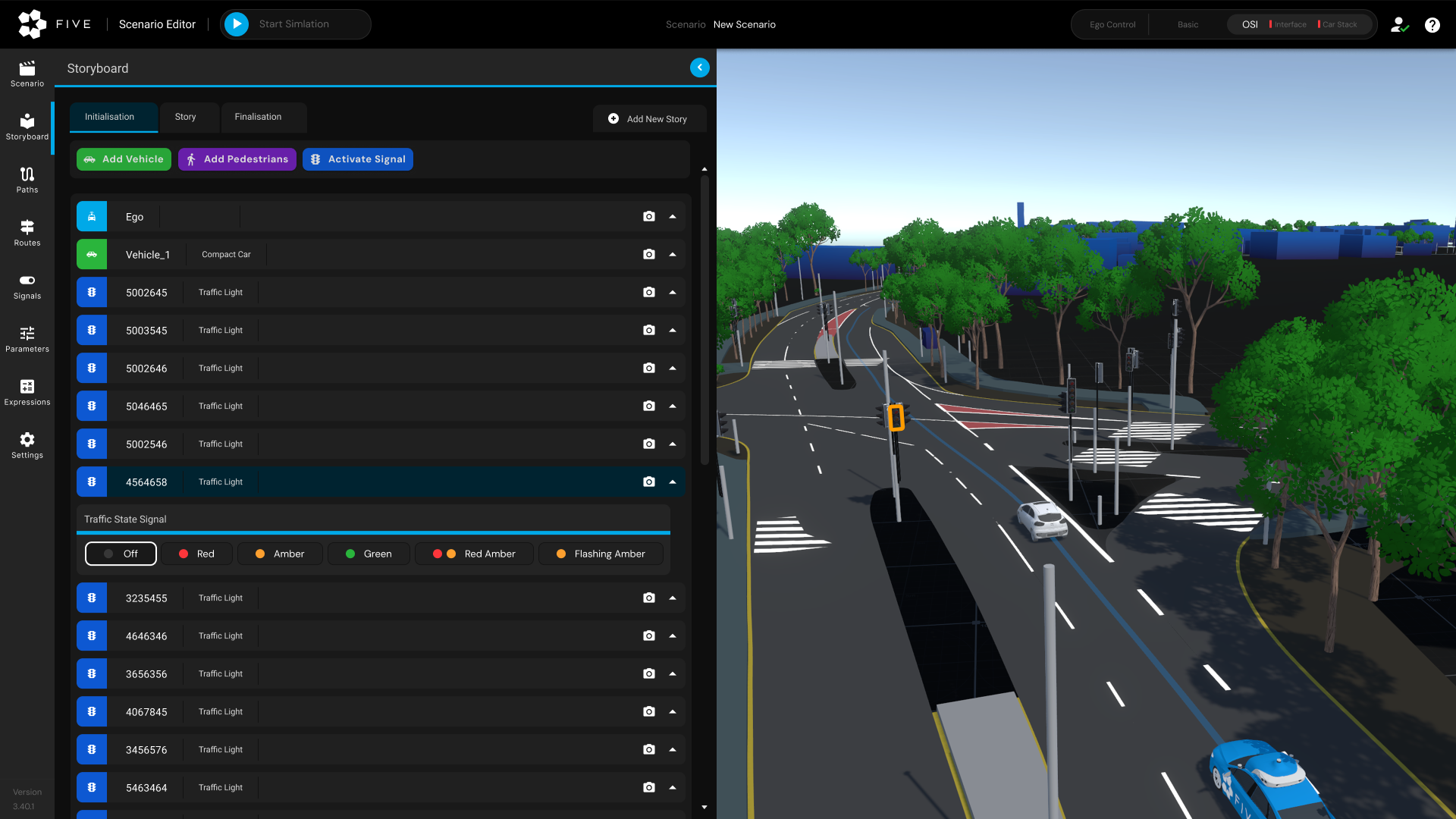
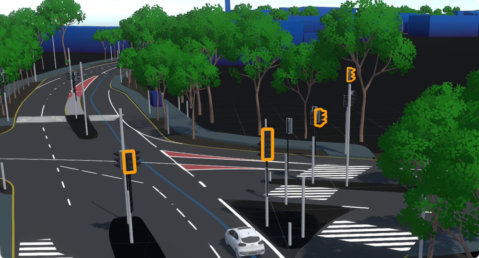
Two mental models had to coexist
Novice users needed to grab a single signal and edit it directly. Experts orchestrating ten-signal roundabouts needed a grouped, synchronised abstraction. Rather than replacing one with the other, I kept both: an Activate Signal path for individual edits and a New Controller path for grouped ones, side by side. Autonomy stays with the user.
Ideation also surfaced two fundamentally different trigger needs: advancing phases on a fixed schedule, or advancing them when an actor reaches a specific position in the simulation. These served different testing goals and both needed to be first-class options.
Activate Signal
Direct per-signal editing for simple scenarios. Engineers who need one light stay on a familiar, fast path.
New Controller
One controller definition drives all member signals through synchronised phases. Define once, orchestrate at any scale.
The Controller Phase panel
Controller Phase panel. Engineers define a phase sequence — Attention, Stop, Go, Stop Attention — set durations, and attach signals as members. Phases are draggable, reorderable tabs. A Reference Another Controller toggle lets multi-crossing roundabouts inherit timing logic rather than duplicating it.
Trigger modes. Time-based mode sets a fixed duration per phase. Position-based mode ties a phase change to an actor's relative position — synced to the 3D viewport so engineers could visually confirm the trigger point. Critical for SOTIF and AI Planner edge-case testing.
An engineer creates a controller once, defines its phases — Attention, Stop, Go, Stop Attention — with durations, then adds any number of individual signals as members. Every member signal moves through phases in lockstep. Change the controller, every linked light updates.
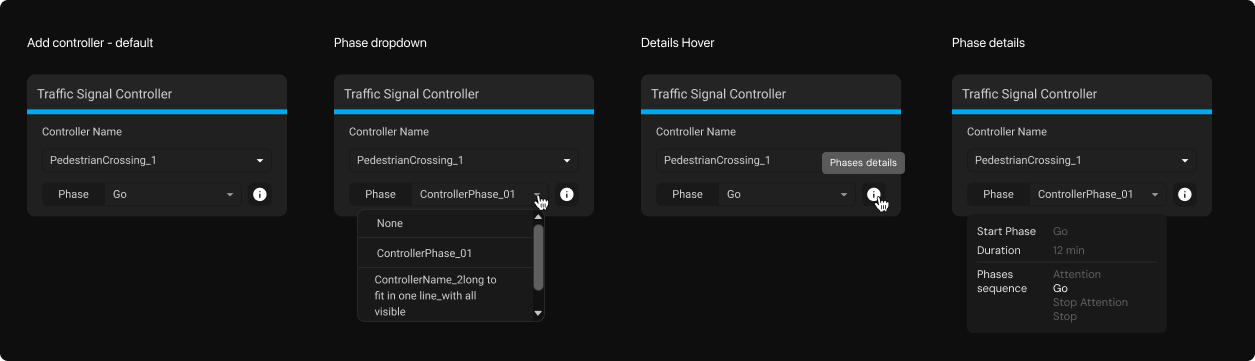
Controller settings configured directly in the scenario
Time-based trigger
A fixed duration per phase — the default path for most junctions. Engineers set it once and the controller steps through automatically.
Position-based trigger
A phase change tied to an actor's relative position in the simulation — synced to the 3D viewport so engineers could visually confirm the trigger point rather than guess at coordinates. Critical for SOTIF and AI Planner edge-case testing.
Where the abstraction broke
Usability testing surfaced a new failure mode: a perfectly synchronised controller could still be placed with no relationship to the road's physical stop line. I added a validation layer — road wireframes for lane boundary visibility and a check flagging misaligned stop points — directly from watching engineers debug, not from the original brief.
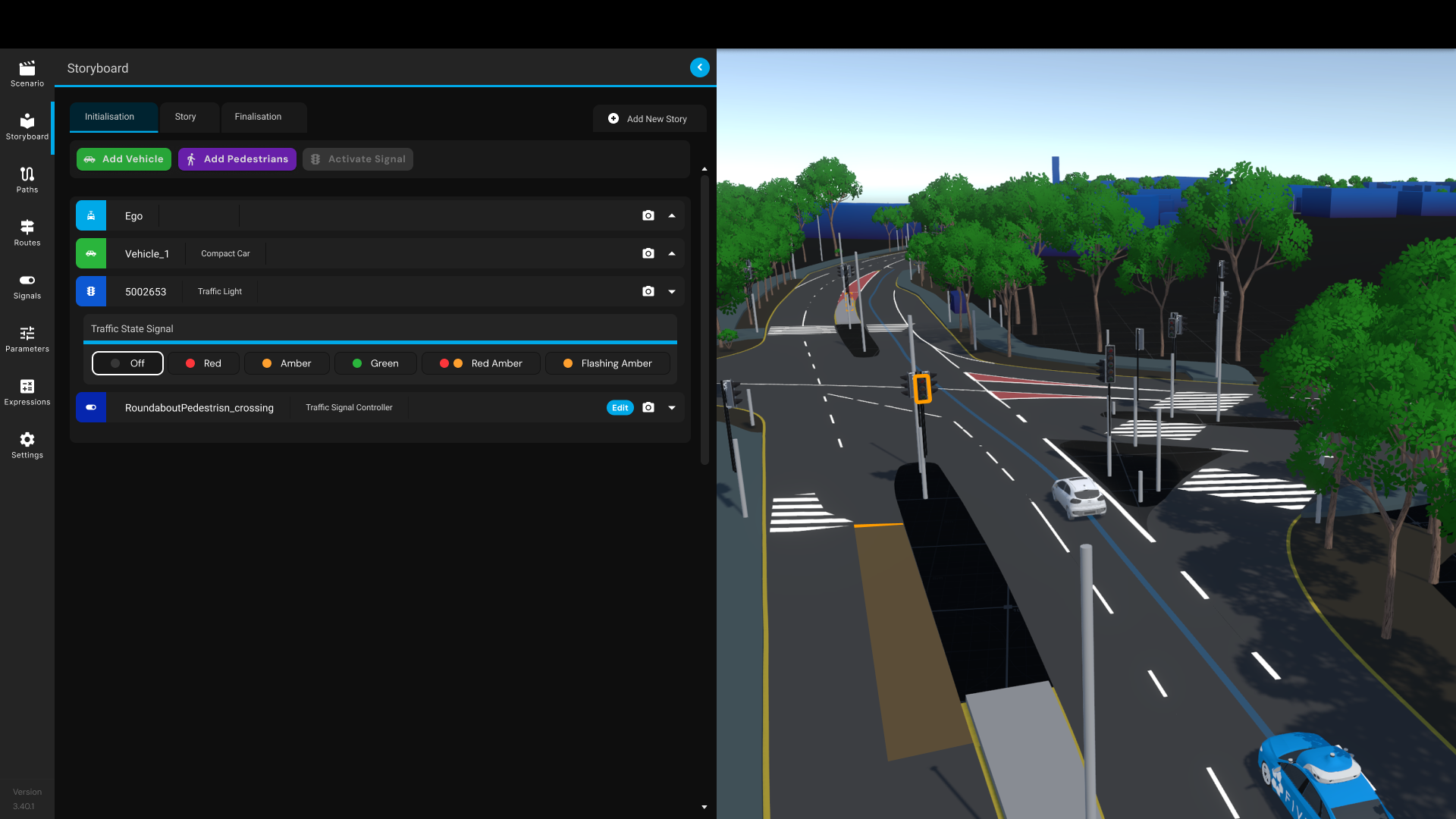
Road wireframe and stop line validation added after usability testing
It reduced configuration errors and made complex intersections genuinely readable — exactly what we needed to trust them at scale.
This could become an AI agentic workflow
If I revisited this today, the manual grouping step is still the bottleneck. Full automation was out of scope for a five-engineer team on a fixed timeline. The next step: an AI agent reads the map, proposes signal groupings and phases automatically, and the engineer just verifies before building the scenario.
Propose-and-verify cuts the manual grouping work further than the controller model alone did.